Sunny: a solar tracker
Sunny is a solar tracker built in 2018-2019 for the ISN option of a final year of French high school, by a team of three. It is a frame designed to turn a flat panel toward the sun. My share was the Arduino code, part of the construction, and the website.
This is the decision record, written from what survives: the bench sketch, the repository README, and the project site. Every entry below is a choice that was made, with the constraint behind it and the arithmetic that supports it.
What was built
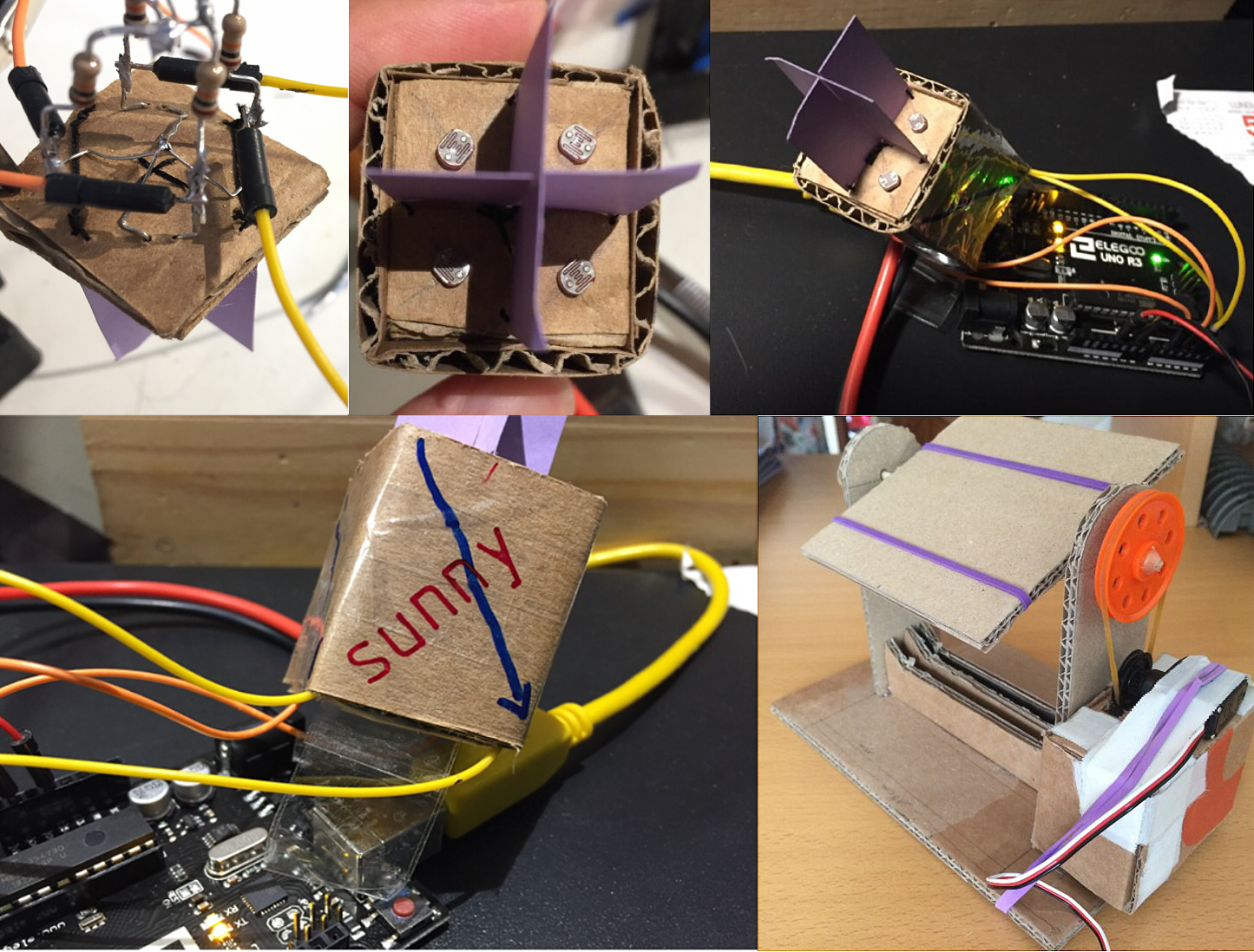
DR-01 | How to find the sun
Three methods were written up before anything was built. Only one was built.
- Chosen: optical, four cells behind a shadow vane. Recorded as simple, cheap, and needing no position fix. Recorded weakness: it stops working when the light drops too low.
- Rejected: compute the sun position from equations. Written off at the time as needing precise coordinates, that is to say a GPS module, which the project did not have. It was also credited with the one real advantage: it works whatever the weather.
- Rejected: a camera, keeping the brightest point centred. Not rejected on merit; there were only so many weeks, and three of them had already gone into an earlier idea that was abandoned.
The optical head carries no state. It needs no clock, no coordinates and no almanac, because its reference is the shadow standing in front of it: the same head works on any roof at any latitude with nothing entered and nothing configured. An equation-driven tracker has to be told where and when it is before it can point anywhere, and every one of those inputs is a thing that can be wrong. The recorded weakness follows from the same property: a head that reads a shadow needs enough light to cast one.
DR-02 | Four cells around a vane
The head is a shallow cardboard box divided into four quadrants by a card cross standing on the centre line, with one photoresistor per quadrant. The cross is the whole sensor: it is an occluder, and the four cells read the shadow it throws. The 2019 notes call this an omnidirectional sensor. What it is precisely is a four-quadrant differential head, and the difference between opposite pairs is the error signal in each of two axes.
sensor head | geometry from above from the side
+---------+---------+ | vane
| | | |
| (o) | (o) | --(o)-----+-----(o)-- plate
| | |
+---------+---------+ sun on the left, so the
| | | vane shadows the right-
| (o) | (o) | hand cell; the drive goes
| | | toward the lit pair until
+---------+---------+ the two counts match
(o) = photoresistor, one per quadrant
the vane stands on both centre linesThe useful property of a differential head is that it does not need a calibrated absolute reading. Nothing has to be converted into lux; the loop only has to drive the difference between two cells toward zero. Absolute accuracy cancels out of a difference, and so does drift, as long as it is common to both cells: the two sit on the same plate, under the same glass, at the same temperature, so most of what would spoil an absolute reading spoils both of them equally and subtracts away. That is what makes four cheap cells sufficient here where one calibrated one would not be.
DR-03 | Photoresistors on a divider
The cells are photoresistors (the round type with the visible serpentine track in the photographs), each wired as one leg of a divider into an analog input. This needs no amplifier, no op-amp, no external converter: a resistor, a cell and one ADC pin per channel.
one channel of four +5V
|
[LDR] one of four, nominally identical
|
+--------> A1 .. A4 ADC input
|
[ R ] fixed leg
|
GNDEither order works and the two invert the sense of the reading: with the cell on top, more light gives a higher count; with it underneath, a lower one. The sketch prints raw counts, and for a differential head the sign convention only has to be consistent, not correct.
The fixed leg is the component that decides how much of the converter's range the sensor actually uses. A divider swings widest when that resistor sits near the geometric mean of the cell's bright and dark resistance. For a cell running 1 kohm in full sun and 100 kohm in shade:
sizing the fixed leg R = sqrt(R_light x R_dark)
= sqrt(1k x 100k) = 10 kohm
Vout at 1 kohm = 5 x 10k / (1k + 10k) = 4.55 V -> 931 counts
Vout at 100 kohm = 5 x 10k / (100k + 10k) = 0.45 V -> 93 counts
usable swing ~ 838 of 1024 counts, centred in the rangePick the resistor an order of magnitude off that mean and the swing collapses into one end of the scale, where the counts still change but the resolution per unit of light does not. The head's sensitivity is set by this one passive component, not by the code.
DR-04 | Arduino Uno, and what its converter actually gave
The Uno was chosen on what it could do. The head needs four analog inputs and the Uno brings six, all on one multiplexed 10-bit converter, so the four cells are read by the same hardware through the same reference and share whatever error it has: exactly the common-mode cancellation the differential head depends on. Four separate converters would have been worse. It also drives a servo off the same 5 V rail and talks to a host over USB without a programmer, which covers actuation and instrumentation on one board. The second reason was deliberate too: the project was framed from the start as a way into the Arduino toolchain and a language close to C.
The header comment of the bench sketch is the specification the rest of this post is quoted from: ATmega328P at 16 MHz, a 10-bit converter spanning 0 V to 5 V, so 1024 counts of about 4.9 mV each.
The first thing built was not the tracker. It was the instrument: a sketch whose only job is to walk the four channels and print them, so the head could be plotted before anything was allowed to move. That order was the right instinct.
test-V0.2-Sunny | bench sketch, 2019/* Home-made sensor of four photocells, one per analog pin (1 to 4).
The loop walks them and prints each value to the console, so the
readings can be plotted afterwards.
Converter: Arduino Uno, ATmega328P at 16 MHz, so a 10-bit ADC
spanning 0 V to 5 V -- 1024 counts, about 4.9 mV each. */
int valReception = 0;
void setup() {
Serial.begin(9600);
}
void loop() {
// 5 ms between reads so as not to overload the ADC
for (int i = 1; i <= 4; i++) {
valReception = analogRead(i);
Serial.print(" Sensor");
Serial.print(i);
Serial.print(" : ");
Serial.print(valReception);
delay(5);
}
Serial.print("\n");
delay(100);
}Comments and the console label are translated from the French original; the code itself is untouched. It was published on its own in 2019 and is not in the project repository, which holds the website and not the sketch. Four things in it are worth pulling out.
- One converter, four channels. The ATmega328P has a single ADC behind a multiplexer, so the four cells are read in sequence and never simultaneously. Here they are 5 ms apart, which does not matter for a shadow that moves at the speed of the sun, but it is a property of the hardware and not an implementation detail.
- The 5 ms comment is wrong. The converter does not need to be rested between
conversions, and
analogReadalready blocks until the conversion it started has finished. What the delays actually do is pace the serial console so a human can read it. That is a fine reason; it just is not the reason written down. - The loop starts at 1. A0 is left unused, for no reason other than the loop counter being convenient to start at one: a usable analog input left on the table by an off-by-one that nobody ever noticed.
- The budget was never a problem. One frame of four channels every 4 x 5 ms + 100 ms ~ 120 ms is about eight frames a second, roughly thirty conversions a second. The header comment reckons the converter could do on the order of ten thousand samples a second, so the sketch used a fraction of a percent of it.
The budget is worth doing properly, because it settles whether any of the pacing mattered. The ATmega328P's converter needs 13 ADC clock cycles per conversion, and that clock is the system clock through a prescaler, /128 by default:
conversion budget ADC clock = 16 MHz / 128 = 125 kHz
one conversion = 13 / 125000 = 104 us -> ~9.6 kSa/s
sketch demand = 4 channels / 120 ms = 33 Sa/s -> 0.35 % of it
sun rate = 360 deg / 24 h = 15 deg/h
per frame = 15 x 0.120 / 3600 = 0.0005 degThe converter runs about three hundred times faster than the sketch asks it to, and the sun moves half a thousandth of a degree between one frame and the next: three orders of magnitude below anything a cardboard flap on a rubber-band hinge can resolve. The pacing exists to make the console readable by a human, and at this ratio it costs nothing the mechanism could have used.
DR-05 | 9 g servos, and the structure that followed
The moving axis is driven by a 9 g hobby servo; the notes talk about the servos in the plural, one per axis. Nothing here was chosen against a torque budget: the servos were what could be afforded, alongside a recorded funding problem covering the solar panel, the servos themselves, and a stepper motor that was considered and never bought.
Everything mechanical about Sunny follows from that one line, and the chain is traceable. A 9 g servo of the common type holds on the order of 1.5 kg.cm at 4.8 V. Torque at the load is that figure divided by the arm, so the usable force at the edge of the panel falls off with how far out it sits:
force at the panel edge T ~ 1.5 kg.cm at 4.8 V
arm 5 cm -> 1.5 / 5 = 300 g at the edge
arm 10 cm -> 1.5 / 10 = 150 g
arm 15 cm -> 1.5 / 15 = 100 g
and that is the stall figure: usable holding
torque is a fraction of it, and it has to cover
the panel, the frame and any wind on the faceA hundred grams of budget at the edge of a flap is what selects the material. Cardboard, rubber-band hinges and a plastic pulley are not what you reach for once that number is on the page; they are the only things that fit under it. The project's own write-up lists the difficulty in exactly those terms: the mass of the components, the stiffness of the cardboard, and the power of the servos. The pulley is doing real work in that chain, and it is the one part of the drive that buys torque back rather than spending it.
DR-06 | Cardboard
Cardboard was the correct choice for a prototype: it is free, it cuts with a knife, and a design mistake costs one more piece of cardboard. Under a 100 g torque budget it is also one of the few materials stiff enough per gram to make the axis move at all. It is the reason the frame could be recut as often as it was inside a school term, and the reason the second axis could be added late without redesigning anything.
DR-07 | Two axes
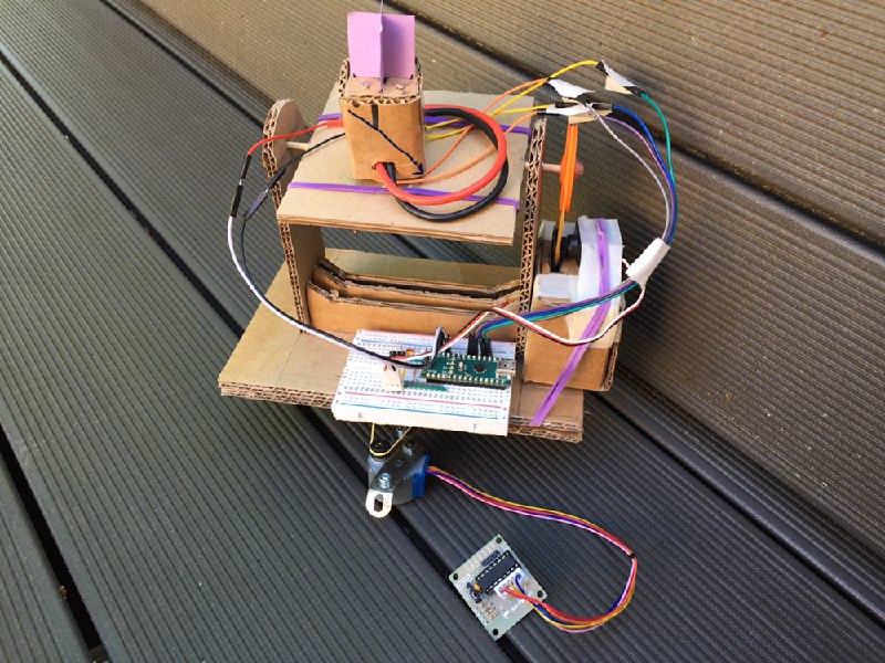
The head reads two axes and the finished mechanism drives both. The first build turned on one, which is what the earliest gallery captions describe; the second stage went on later and the last version tracked in both directions cleanly. It is the arrangement in the photograph below: the lower deck carries the board and the azimuth drive, the upper flap carries the head and tilts on the second servo.
Adding the axis late worked because the two are independent. A four-quadrant head produces one error signal per axis from the same four readings, so the second loop is the same code against a different pair of cells and a different pin. Nothing in the sensing side had to change to accommodate it.
DR-08 | The web side
The plan was a site showing the tracker's state, its voltage, its position and some statistics, with a PHP page as the endpoint and a small mobile application built in App Inventor alongside it. All three were built, and in the last version the link was closed: the tracker reached the PHP endpoint and the page showed live state. It was a proof of concept rather than a product. The transport was not clean, there was no schema worth the name, and nothing about it was hardened. It ran.
What the project's own conclusion still lists under future improvements is remote control, which is the harder half: reading state out is one direction, and commanding the mechanism from the page is the one that was never attempted.
What holds up
The sensing principle is sound and cost almost nothing: an occluder and four cheap cells give a differential null that needs no calibration in physical units, no coordinates and no clock. The order of work was right, the instrument before the machine and the bench sketch before the servo, which is why there are numbers to quote at all. And the constraint chain runs cleanly from one end to the other: a torque figure sets a mass budget, the mass budget selects a material, and the material decides how the axis is hinged. Each link is checkable, which is the part that makes it a decision record rather than a build log.
The machine tracked in two axes and the telemetry reached a page. Everything still standing is on the original project site and in the repository, both still up and still in French.