exploRob
exploRob is a tracked robot with a gripper on it, built for exploring: driving somewhere I would rather not walk, picking something up when it gets there, and reporting what the air is like on the way. There have been two of them: an early build on a Makeblock chassis with a boom arm bolted to it, and a lower second one that gave up the arm for a real battery pack and better electronics.
Both are driven by hand. Neither navigates on its own and neither knows where it is; there is a camera on the front and a person at the other end of a radio link. The part worth writing about is the electronics, so that is what this is.
The first robot
Rubber tracks, an aluminium chassis, and a boom arm. The main gripper hangs off the end of the boom on a 1:144 gearmotor. Slow, and with enough torque that whatever it picks up stays picked up. The secondary gripper is built out of 9 g servos: it moves on more axes than the main one, so it is the better of the two for fiddly work, and it will not lift more than about 9 g. That is the whole trade, and it is a fair one.
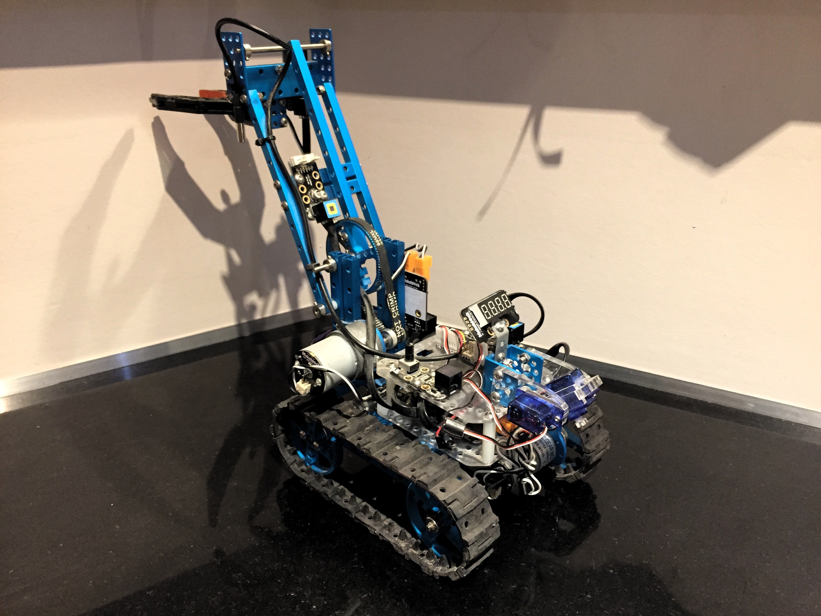
The rest of what it carries:
- A camera, so it can be driven out of sight.
- A potentiometer, for last-minute adjustment and calibration without a laptop.
- A four-digit seven-segment display.
- Two converter breakouts (ADC/DAC), so more sensors can hang off the same few pins.
- A fan. Exploring in full sun in summer overheats it, and the first symptom of overheating is not a stall; it is the radio link dropping out.
- An HM-10 Bluetooth module.
- A thermometer.
- A photodetector. A photodetector, not a photoresistor.
- A headlight made of four RGB LEDs.
Electronics
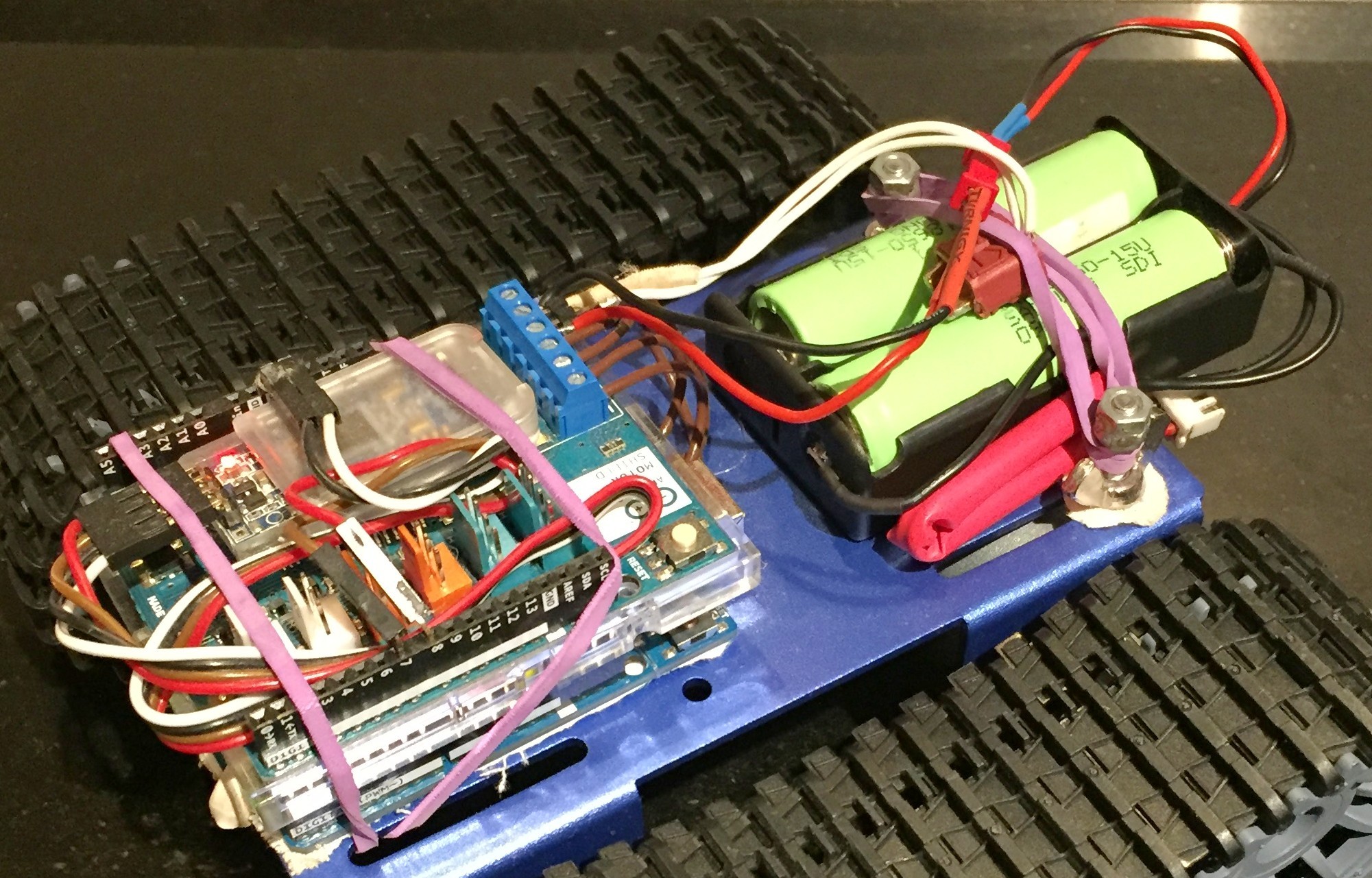
The second build is where the wiring got tidier, and it is the one the notes below describe.
- Controller. An ATmega328P at 16 MHz. It is not a fast part, but everything on this robot that has to happen on time (the motor control loop, the sensor reads) happens in a hardware interrupt, and interrupts are what this chip is good at. The Arduino ecosystem around it meant I could write a motor routine instead of a bootloader.
- Servos. PWM generated by the MCU's hardware timers rather than by a software loop, so servo pulses keep their timing while the main loop is busy elsewhere.
- Drive. The chassis DC motors run through an L298N H-bridge, kept isolated from the command logic so that back-EMF and switching noise from the motors do not travel back up the line into the controller.
- Sensor bus. An I2C bus at 400 kbps as the spine. Two wires for everything, and adding a device means giving it an address instead of finding two more free pins.
- Power. A 2S lithium-ion pack, 7.4 V nominal. Low-dropout regulators split it into a 5 V rail for the logic and the servos and a 3.3 V rail for the sensors that prefer it, with filtering and decoupling done per subsystem: the servos and the motors are the noisiest things on the robot, and they share a battery with everything that is not.
- Environment. A BME680: pressure, temperature, humidity, and volatile organic compounds. The VOC channel is the reason it is fitted. It is the difference between reporting a temperature and reporting that something in the air has changed.
The 9 V block, and why it left
Version 0.3 ran off a 9 V block battery. The voltage was never the problem. The current was: a 9 V block gives 9 V and nowhere near enough amperage for two DC motors and a handful of servos that all decide to move at the same instant.
It came out and two lithium cells in series went in: 7.4 V nominal, and an amperage that is actually adequate. There is a short film shot from the robot itself, from back when it was still on the 9 V pack: exploRob, on YouTube.
The transmitter
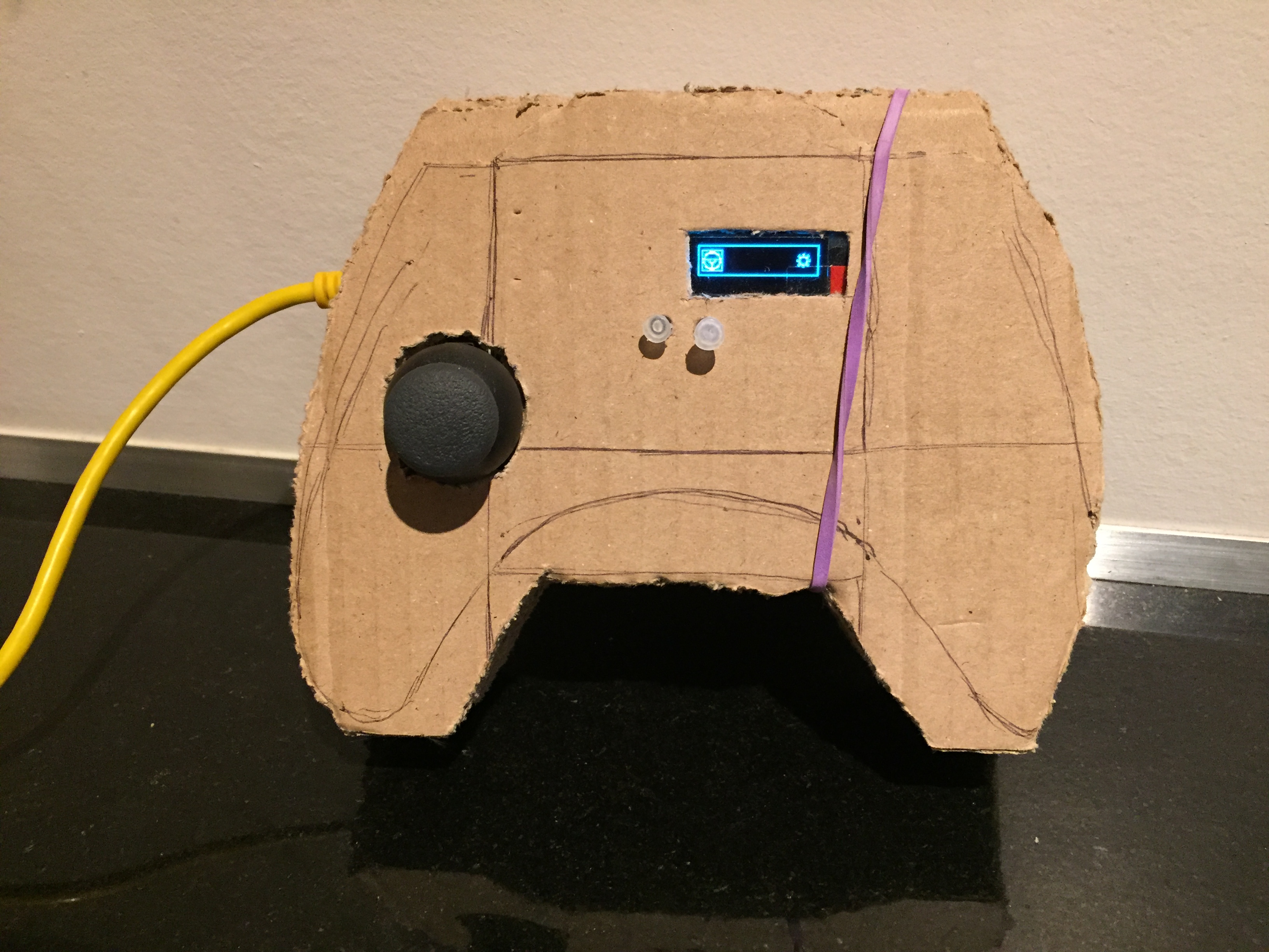
The remote is a sheet of cardboard cut to the outline of a game controller. The outline was drawn on it in pencil first and the pencil lines are still there. One thumb joystick, two buttons, a small OLED for the menu, and a rubber band holding the whole thing shut.
Inside: an Arduino with a prototyping shield, a mini breadboard, four tactile buttons wired into it, the joystick module on jumper leads, a Bluetooth module on a breakout, and the OLED. It was assembled on the component inventory sheet of the starter kit most of it came out of, which is visible under the wiring and is the most honest thing in the photograph.
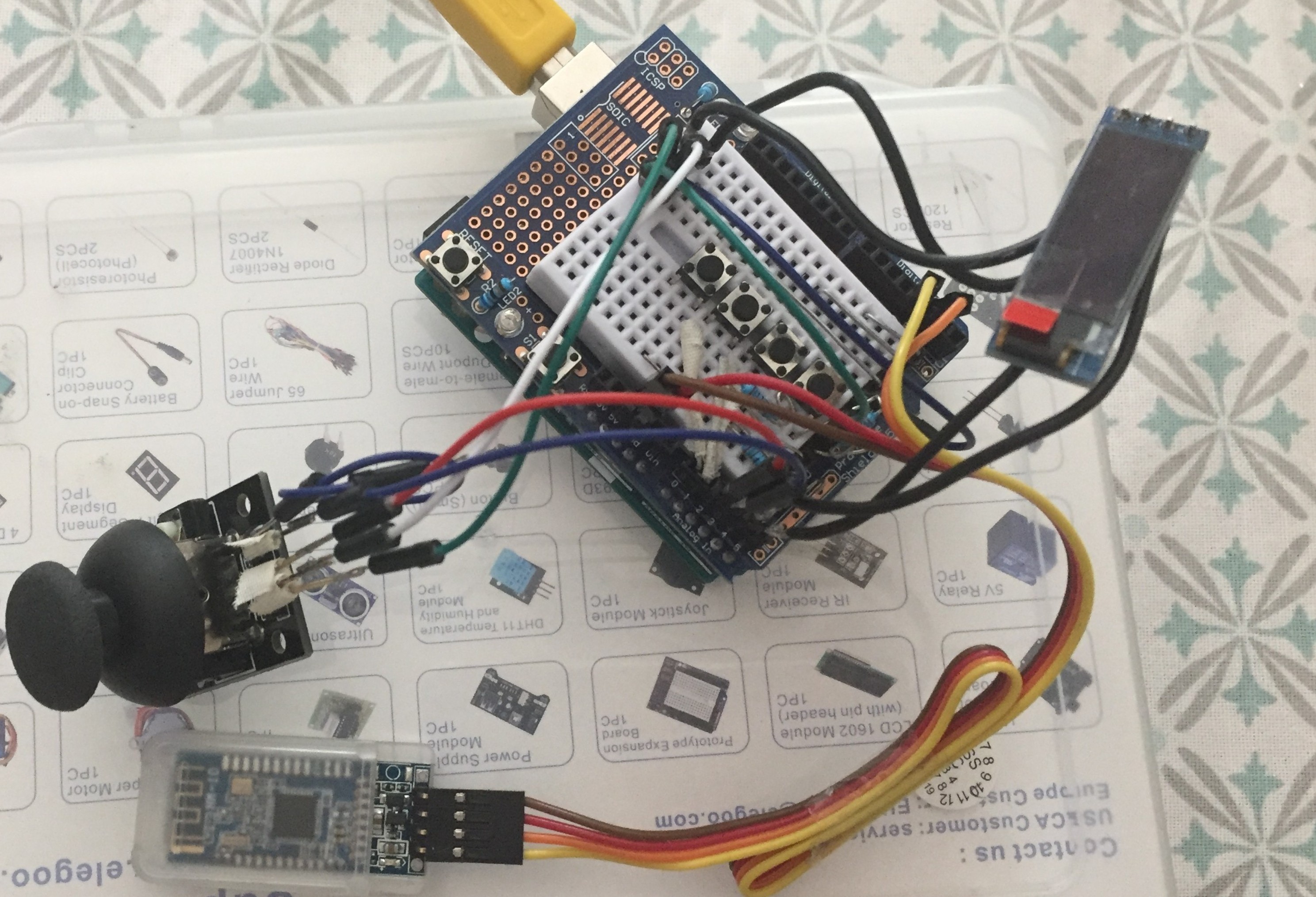
It is cardboard and I would build it out of cardboard again. The shell is the cheapest part of a remote to get wrong and the most expensive to get right, and cardboard lets you cut the hole in the wrong place twice.
The link, in the last version
Every photograph on this page is of an earlier revision. The last revision dropped the Bluetooth module and ran the same 2.4 GHz link and the same protocol I had written for the boat: a packed C struct with an explicit field layout, an integrity field with a standard error-handling scheme over it, a session handshake, and a lightweight cipher on the command traffic.
The Open Boat post covers the frame format and why the struct is packed. Two things about it read differently on a tracked robot than they do on a boat.
- Range is not a comfort feature. A boat you cannot reach drifts, and it drifts somewhere you can still see it. A robot you cannot reach is a robot you walk to, and walking to it is the thing the machine exists to avoid. Moving to a longer-range radio is the clearest evidence of what the constraint was worth.
- A lost frame on two driven sides is a heading, not a pause. The frame is validated as a unit, so a corrupted one is rejected whole and no track ever receives an update the other missed. The hazard is staleness rather than partial application: hold the last good command through an outage and a differential drive keeps turning, which on a boat is a slow arc and on tracks is a new direction.
Not built
This is the part that stayed on paper.
- A second processor: a Linux single-board computer alongside the ATmega, so the microcontroller keeps the real-time work and something larger handles anything above it.
- A range sensor and an inertial measurement unit, so the robot could build a map of where it has been instead of being driven blind through a camera.
- Navigation on top of that map, which is the only reason to want the map.
None of it exists. The robot in the photographs is driven by hand, over Bluetooth, from a cardboard controller with a rubber band around it.